This page is the mathematical model behind the entry page and the explorer: it shows that the animation is computed from a physical model, not drawn. The idea is told on the entry page, and the case is read through, with its numbers, on the technical page.
Writing rules: every quantity is shown in a figure before it enters a formula; quantities and their sources are in the table of section 6.2; equations are cited as eq. (N); a bare number always denotes an element of the patent, written with its name (“guide pulley 17”).
1. Objective
A rear derailleur has one task: to move the chain from one sprocket of the pack to the next and keep it properly engaged on each, with a single setting of the derailleur. The guide pulley, the upper wheel of the cage, steers the chain; the chain leaves the sprocket in use, runs a free stretch to the pulley and goes on to the chainring.
The model answers one question: with the pulley set once at a given gap under the largest sprocket, how constant does the gap between pulley and sprocket stay across the whole pack, with the pulley moving on a straight path (the known way) and on a path slanted as the patent describes? And where does the slanted path stop fitting the pack?
The reference case is the five-speed pack of the 1960s, 14–24 teeth. The other packs of the explorer (up to the 12-speed 10–50 of today) are the domain of section 9.
2. Specifications
S1 — One setting serves the whole pack. The gap \(g\) between the pulley and the sprocket in use must stay close to the value set on the largest sprocket, on every sprocket. This is the first characteristic of the patent: the guide pulley moves along a line parallel to the line connecting the lower brims of the sprockets, so that the space between pulley and sprocket is kept constant.
S2 — A step of the cage must tilt the chain enough. The shorter the free stretch of chain, the more steeply one step of the cage tilts it, and the sooner the chain is pushed onto the next sprocket. The model computes the free span \(L\) and the tilt \(\theta\) of one step as indices of this; it does not compute the capture itself (see section 11).
S3 — The chain tension stays constant with one spring. This is the third characteristic of the patent, obtained with a single helical spring on the convertor (the cage). It is not modelled: it is declared outside the model in section 5.
The second characteristic of the patent, an engaging length of the chain on the sprocket that stays nearly the same, follows from S1 and is not modelled either.
3. Elements and patent references
Element names are fixed here and used unchanged in the other documents, in the figures and in the explorer. References are those of US 3,364,762. Each reference is listed with the patent figure where it can be seen, so that the reader can follow the mechanism on the drawings: figures 1 to 3 below are figures 3, 4 and 2 of the patent.
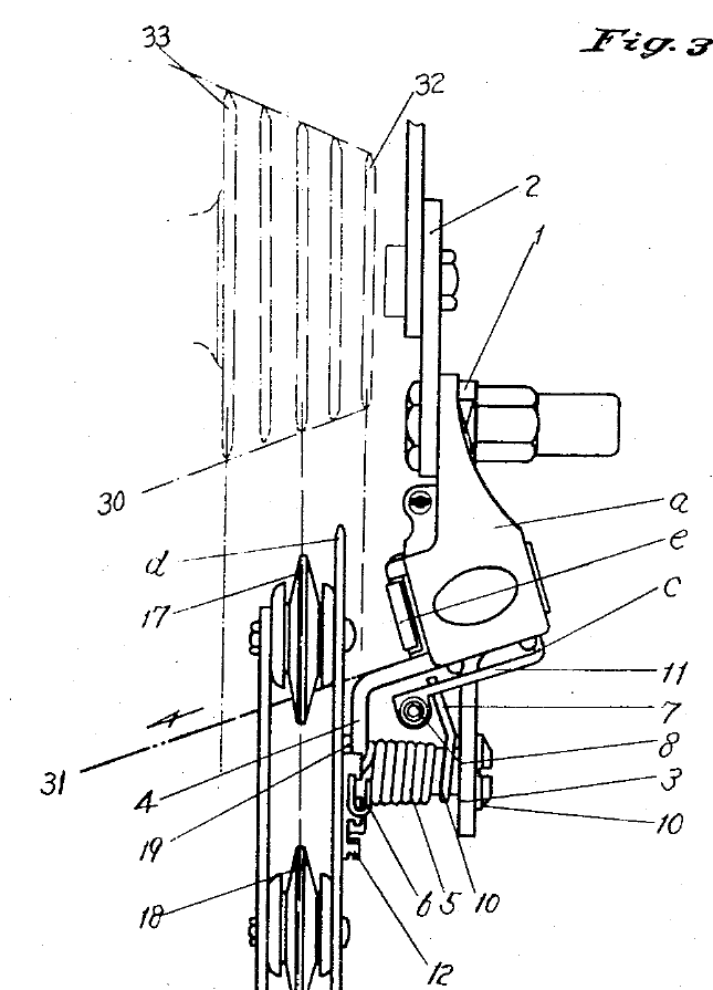
Figure 1. US 3,364,762, figure 3: the derailleur seen from behind, with the sprockets. Line 30 joins the lower brims of the sprockets; line 31 is the direction in which the shifting body moves. Seen here: a, c, d, e, 17, 18, 19, 5, 6, 10, 12, 32.
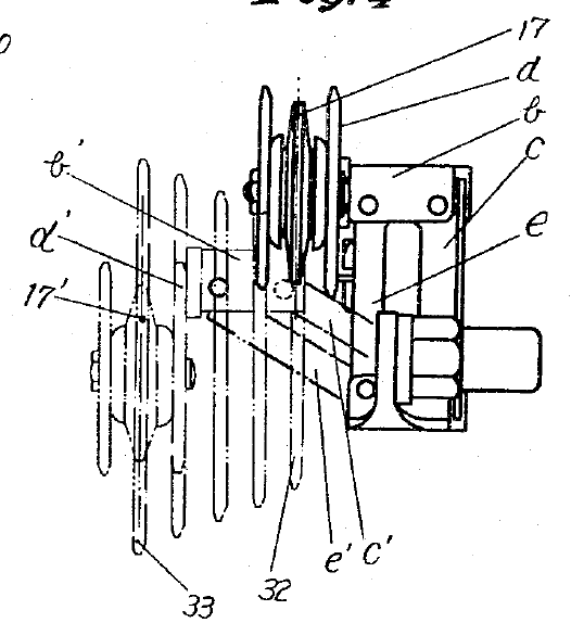
Figure 2. US 3,364,762, figure 4: top plan view with the pack. The parallelogram formed by the support a, the operation tool c, the connecting rod e and the shifting body b is drawn in two positions: b, c, e, d, 17 and b’, c’, e’, d’, 17’. Sprockets 32 (smallest) and 33 (largest).
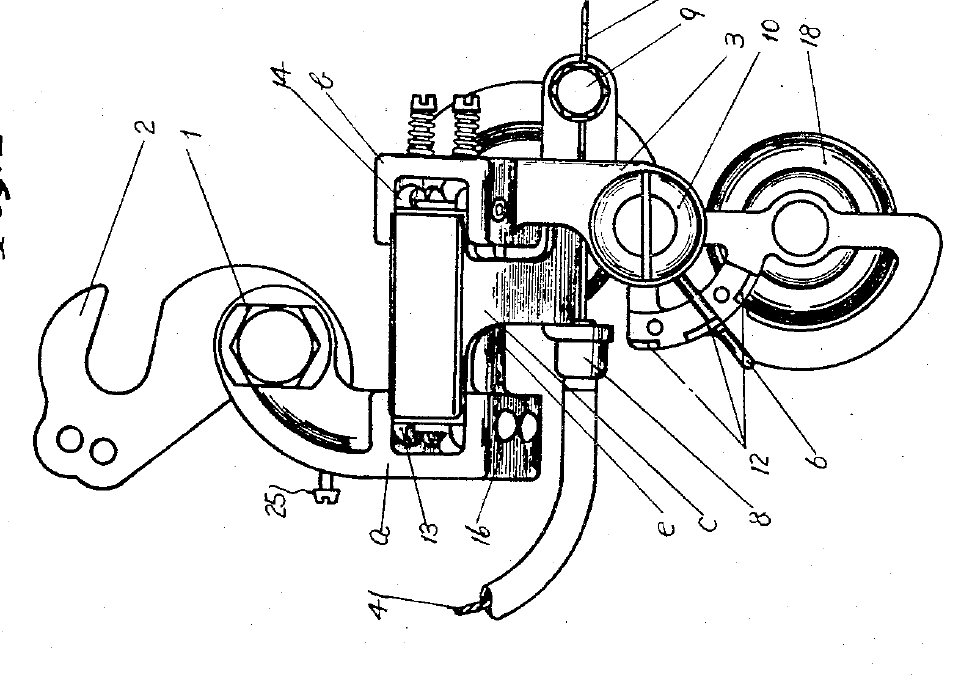
Figure 3. US 3,364,762, figure 2: right end view of the derailleur (rotated). Seen here: the support a with its connecting part 16, the operation tool c, the connecting rod e, the pulley 18, the barrel 8, the clamping bolt 9, the cable 41, the adjusting screw 25, the catches 12 and the end 6 of the spring.
| element | patent reference | seen in figure | role | in the model |
|---|---|---|---|---|
| support | a, with connecting part 16 | 3 (a, 16); 1 (a) | fixed to the rear-wheel hub axle; the connecting part is inclined | yes: gives the slant \(\alpha\) of the path |
| shifting body, operation tool, connecting rod | b, c, e | 2 (b, c, e and the displaced b’, c’, e’); 3 (c, e) | together with a they form the freely revolving parallelogram | yes: the path of the pulley |
| convertor (cage) | d | 1, 2 (d and d') | carries guide pulley 17 and tension pulley 18; turns about pin 10 | pulley 17 yes; rotation about pin 10 no |
| guide pulley | 17 | 1, 2 (17 and 17') | steers the chain onto the sprocket in use | yes: radius \(r\) |
| tension pulley | 18 | 1, 3 | takes up the slack | no |
| helical spring | 5, ends 6 and 7, on pin 10 | 1 (5, 6, 7, 10); 3 (6) | strains the chain and stabilizes the cage | no |
| cable, sheath, adjusting screw | 41, barrel 8, bolt 9, screw 25 | 3 | moves the shifting body obliquely | no: only the position of the pulley is modelled |
| sprockets (change gears) | 32 smallest, 33 largest | 2 (32, 33); 1 (32) | the pack | yes: pitch radius \(R_i\) , spacing \(s\) |
| chain | 40 | text of the patent | yes: pitch \(p\) | |
| line of the lower brims | 30 | 1 | joins the lower edges of the sprockets | yes: gives \(\alpha^*\) |
| shifting direction | 31 | 1 | direction of the shifting body; parallel to line 30 | yes: it is the path of the pulley |
4. How the derailleur works
The support a, the operation tool c, the connecting rod e and the shifting body b form a parallelogram. In the known derailleurs the pulley moves straight sideways, always at the same height. Maeda inclined the connecting part 16 of the support: the parallelogram is slanted, and the shifting body moves obliquely, along direction 31, which is parallel to line 30.
The chain of causes, which the model follows step by step, is this:
- the pulley path is parallel to the line of the lower brims, so the pulley keeps nearly the same gap under every sprocket (S1);
- with a small gap the free span is short;
- a step of the cage across the sprockets then tilts the short span steeply (S2);
- the chain is pushed sooner onto the next sprocket: this link is the argument of the patent, the model gives its geometry, not the capture.
The convertor d is mounted on the shifting body through pin 10 and spring 5. When the chain is laid on a sprocket the convertor turns about the centre of pin 10, moving pulley 17 and pulley 18 from position 35 to position 36 of patent figure 5, which takes up the slack and keeps the tension. This turn also moves the guide pulley along a short arc. The model does not include it (section 5).
5. From the mechanism to the model
| # | what the model does | origin |
|---|---|---|
| H1 | the pulley moves on a straight line in the rear view, with slant \(\alpha\) (\(\alpha=0\) is the known parallelogram) | patent (direction 31); the real parallelogram traces an arc, neglected |
| H2 | the pulley centre is vertically below the wheel axle; the longitudinal offset of patent figure 4 is neglected | assumption |
| H3 | the pulley is set so that its gap on the largest sprocket is \(g_B\) , as the maintenance manuals prescribe for the B-screw, the screw that sets the distance of the pulley from the sprocket | convention of the manuals; the screw is not named in the patent |
| H4 | the gaps are measured between pitch circles; a mechanic measures between tooth tips, a gap smaller by the tooth heights of the two wheels, nearly the same on every sprocket | assumption |
| H5 | the rotation of the convertor about pin 10 (positions 35 and 36 of the patent) and the spring 5 are not modelled: the pulley is taken at the position it has when the chain is strained on the sprocket | exclusion, declared |
| H6 | the capture of the chain by the next sprocket (clearances, inner and outer links, ramps of the teeth) is not modelled | exclusion; kept in the pre-study of the case |
| H7 | the guide pulley has 10 teeth | assumption |
H1–H4 and H7 are what the explorer computes. H5 and H6 are the limits discussed in section 11.
6. Geometry
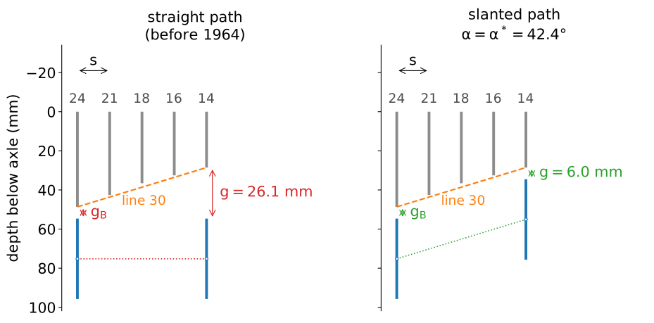
Figure 4. Rear view of the 14–24 pack of the 1960s with the pulley at the two ends of the pack. Left: straight path; right: path slanted by the angle \(\alpha^*\) of line 30. The sprockets are drawn edge-on from the axle down to their pitch circle; the sideways scale is three times the vertical one. The pulley is set once, at the gap \(g_B\) under the largest sprocket; at the other end of the pack the gap is \(g\) .
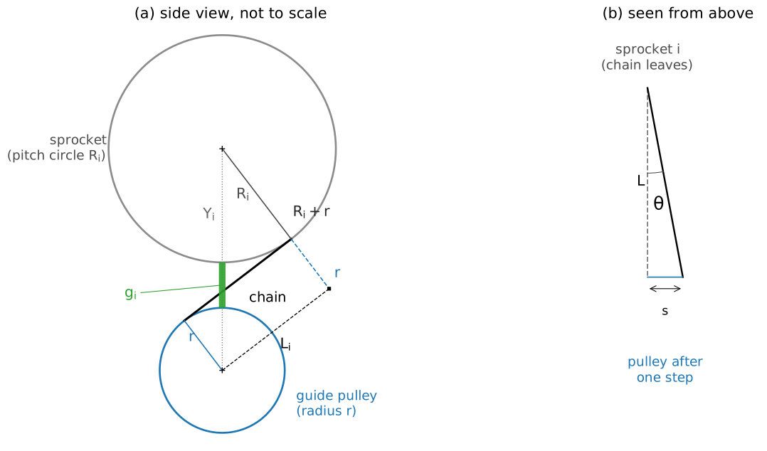
Figure 5. (a) Side view, schematic: the free span \(L_i\) is the stretch of chain between the sprocket and the guide pulley, tangent to both. The radii \(R_i\) and \(r\) are perpendicular to the chain; the radius \(r\) laid off beyond the tangent point gives the point \(Q\) ; the right triangle sprocket centre – \(Q\) – pulley centre has the legs \(R_i+r\) and \(L_i\) and the hypotenuse \(Y_i\) (eq. 4). (b) Seen from above: one step \(s\) of the cage tilts the span by the angle \(\theta\) .
6.1 Chain, sprockets and pulley
The chain pitch is \(p\) . A sprocket of \(z\) teeth has pitch radius \(R\) and the guide pulley has radius \(r\) . The sprockets are numbered from the largest, \(i=0,\dots,n-1\) , with teeth \(z_i\) ; the spacing between adjacent sprockets is \(s\) , so the sprocket \(i\) sits at \(x_i=i\,s\) along the axle, \(x=0\) at the largest sprocket. \(Y\) is the depth of the pulley centre below the wheel axle at the position \(x\) .
6.2 Quantities
| symbol | meaning | value | source |
|---|---|---|---|
| \(p\) | chain pitch | 12.7 mm | standard, 1/2" |
| \(z_i\) | teeth of sprocket \(i\) | per pack | typical packs, assumed |
| \(s\) | spacing between adjacent sprockets | 5.5 mm (5-speed), 5.0 mm (7-speed), 3.74 mm (11-speed), 3.5 mm (12-speed) | Sheldon Brown; Wikibooks; the 12-speed value is assumed |
| \(z_p\) , \(r\) | teeth and radius of the guide pulley | 10 teeth, 20.55 mm | assumed |
| \(g_B\) | gap on the largest sprocket, set once | 6 mm (initial value of the explorer) | manuals give 5–6 mm tip to tip; here between pitch circles |
| \(\alpha\) | slant of the pulley path in the rear view | 0 = straight | patent: parallel to line 30 |
| \(R_i\) , \(g_i\) , \(L_i\) , \(\theta_i\) | pitch radius, gap, free span and one-step tilt on sprocket \(i\) | computed | model |
7. Derivation
7.1 Pitch radius
The chain is made of rigid links, so on a sprocket of \(z\) teeth it does not bend into a curve: each pin sits in a tooth space, and the \(z\) pins form a regular polygon whose side is one chain pitch \(p=12.7\) mm, the distance between the pins of two adjacent links. The pins lie on a circle, the pitch circle, and the pitch radius \(R\) is the radius of that circle (figure 6). The side of the polygon subtends the angle \(2\pi/z\) at the centre, so \(p/2=R\sin(\pi/z)\) :
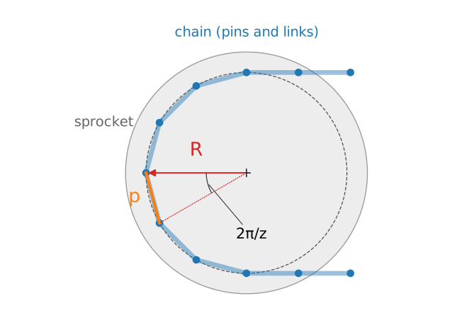
Figure 6. The chain on a sprocket (here \(z=12\) teeth): the pins on the pitch circle of radius \(R\) ; the pitch \(p\) is the distance between two adjacent pins. The pitch radius is the radius at which the axis of the chain runs, not the radius of the tooth tips.
For the pulley \(z=z_p\) gives \(r=20.55\) mm. For the 24-tooth sprocket \(R_0=48.65\) mm and for the 14-tooth one \(R_{n-1}=28.54\) mm.
7.2 Path of the pulley
The pulley is set so that its gap on the largest sprocket is \(g_B\) : the top of the pulley is \(g_B\) below the bottom of the sprocket, as in figure 7. Its centre is then at depth \(R_0+r+g_B\) at \(x=0\) , one radius \(r\) below the top of the pulley. The straight parallelogram keeps this depth for every \(x\) ; the slanted one raises the centre by \(x\tan\alpha\) as \(x\) grows toward the small sprockets:
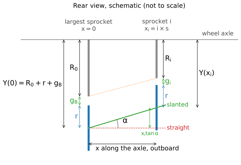
Figure 7. Rear view, schematic and not to scale. Sprockets and pulley are seen edge-on; depths are measured from the wheel axle. At \(x=0\) : the radius \(R_0\) of the largest sprocket, the gap \(g_B\) and the radius \(r\) of the pulley add up to the depth \(Y(0)\) of the pulley centre. At the sprocket \(i\) the path has risen by \(x_i\tan\alpha\) , so \(Y(x_i)=Y(0)-x_i\tan\alpha\) and the gap is \(g_i=Y(x_i)-R_i-r\) (eq. 3).
with \(\alpha=0\) for the straight parallelogram.
7.3 Gap
The gap on the sprocket \(i\) is the distance between the pulley centre and the sprocket centre, less the two radii:
Here \(i\,s=x_i\) is the position of the sprocket \(i\) (section 6.1): \(i\) is the number of the sprocket counted from the largest (\(i=0,1,\dots\) ) and \(s\) the spacing between adjacent sprockets, so \(i\,s\) is the sideways distance from the largest sprocket and \(i\,s\tan\alpha\) the rise of the path over it.
7.4 Free span
The chain leaves the sprocket, runs straight to the pulley and wraps it on the opposite side: it crosses between the two wheels, in an S. The straight stretch is therefore the internal common tangent of the sprocket circle and the pulley circle (figure 5a); its length \(L_i\) is the free span. It follows from a right triangle, built in three steps:
- The chain is tangent to both circles, so the radius \(R_i\) of the sprocket and the radius \(r\) of the pulley, drawn to the two tangent points, are both perpendicular to the chain. Because the chain passes between the wheels, the two radii point to opposite sides of it.
- Lay off the radius \(r\) beyond the tangent point on the sprocket, along the line of the radius \(R_i\) : it ends at the point \(Q\) , at the distance \(R_i+r\) from the centre of the sprocket.
- The segment from \(Q\) to the centre of the pulley is parallel to the chain and as long as the free span, \(L_i\) , because the radius \(r\) of the pulley and the segment laid off beyond the tangent point are the two equal sides of a rectangle with the chain. At \(Q\) the angle is a right angle.
The triangle has the hypotenuse \(Y_i\) , the distance between the centres, which is \(R_i+r+g_i\) by the definition of the gap, and the legs \(R_i+r\) and \(L_i\) . By Pythagoras:
The second form is obtained by writing \(Y_i=(R_i+r)+g_i\) and expanding \(Y_i^2-(R_i+r)^2=g_i\,(2(R_i+r)+g_i)\) . If the chain wrapped both wheels on the same side (external tangent) the legs would be \(R_i-r\) and \(L_i\) : this is not the arrangement of a derailleur, where the pulley turns in the sense opposite to the sprocket.
7.5 Tilt of one step
When the cage steps by \(s\) toward the next sprocket the free span, still of length \(L_i\) , is displaced sideways by \(s\) . Its tilt is
A shorter span gives a larger \(\theta\) . This is an index of how steeply the cage pushes the chain toward the next sprocket; it is not a capture condition.
7.6 The slant of the patent
Line 30 joins the lower brims of the largest and the smallest sprocket. Its slope in the rear view is
With \(\alpha=\alpha^*\) the gap on the smallest sprocket is, by eq. (3), \(g_{n-1}=g_B+(R_0-R_{n-1})-(n-1)s\tan\alpha^*=g_B\) : the gap is \(g_B\) at both ends of the pack. For the 14–24 pack \(\alpha^*=42.43°\) .
7.7 The residual
For \(\alpha=\alpha^*\) eq. (3) becomes
which is the distance of the lower brim of the sprocket \(i\) from line 30, because the lower brims are the points \((x_i,R_i)\) . They are not on a straight line, so in between the two ends the gap differs from \(g_B\) . The residual is the spread of the gap on the pack:
For the straight path (\(\alpha=0\) ) eq. (3) gives \(g_i-g_B=R_0-R_i\) , which is the largest on the smallest sprocket:
For the 14–24 pack: \(\Delta g_{straight}=20.1\) mm against \(\Delta g=2.0\) mm with the slanted path.
8. Conditions and setting
The setting has two steps, as in the patent and in the manuals:
- the B-screw is set so that the gap on the largest sprocket is \(g_B\) (assumption H3);
- the slant of the path is \(\alpha=\alpha^*\) of eq. (6), i.e. the path is parallel to line 30.
Then \(g_0=g_{n-1}=g_B\) and the gap on the sprockets in between is given by eq. (7). The only residual is \(\Delta g\) of eq. (8). In the explorer the slant \(\alpha\) can be moved by hand, and the button “Match the pack” sets \(\alpha^*\) .
9. Domain
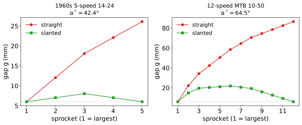
Figure 8. Gap on every sprocket with \(g_B=6\) mm, for the straight and the slanted path (\(\alpha=\alpha^*\) ). Left: the 14–24 pack of the 1960s; right: the 12-speed 10–50 pack of today.
On the 14–24 pack the slanted path keeps the gap between 6.0 mm and 8.0 mm; the straight path lets it grow from 6.0 mm to 26.1 mm. The free span goes from 25.0 mm to 31.3 mm against 29.4 mm to 57.0 mm, and the tilt of one step stays between 10.0° and 12.4° against 5.5° and 10.6°.
On the 10–50 pack the slanted path fits the two ends of the pack, but the lower brims bend away from line 30: the gap rises from 6.0 mm on the largest sprocket to 21.9 mm and returns to 6.0 mm on the smallest.
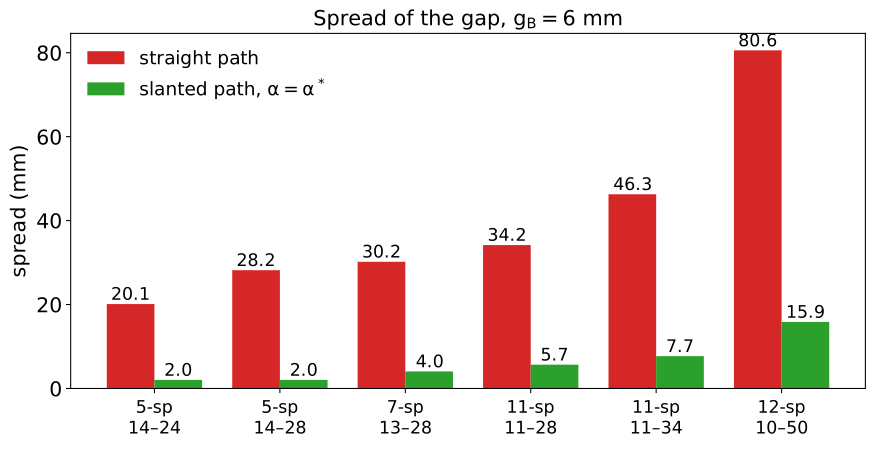
Figure 9. Spread of the gap \(\Delta g\) on the six packs of the explorer, with \(g_B=6\) mm, for the straight path (eq. 9) and for the slanted path at \(\alpha=\alpha^*\) (eq. 8).
| pack | spacing \(s\) | \(\alpha^*\) | gap, straight [mm] | gap, slanted [mm] | \(\Delta g\) straight [mm] | \(\Delta g\) slanted [mm] |
|---|---|---|---|---|---|---|
| 1960s 5-speed 14–24 | 5.5 mm | 42.4° | 6.0–26.1 | 6.0–8.0 | 20.1 | 2.0 |
| 1970s 5-speed 14–28 | 5.5 mm | 52.0° | 6.0–34.2 | 6.0–8.0 | 28.2 | 2.0 |
| 7-speed 13–28 | 5.0 mm | 45.2° | 6.0–36.2 | 6.0–10.0 | 30.2 | 4.0 |
| 11-speed road 11–28 | 3.74 mm | 42.4° | 6.0–40.2 | 6.0–11.7 | 34.2 | 5.7 |
| 11-speed 11–34 | 3.74 mm | 51.1° | 6.0–52.3 | 6.0–13.7 | 46.3 | 7.7 |
| 12-speed MTB 10–50 | 3.5 mm | 64.5° | 6.0–86.6 | 6.0–21.9 | 80.6 | 15.9 |
The slanted path reduces the spread by a factor of ten on the pack of the patent’s time, and by a factor of five on the widest pack of today, where the spread is still 15.9 mm: the wider the pack, the more the lower brims depart from a straight line.
10. Explorer
The explorer computes eq. (1)–(9) live in the browser with the same formulas as US3364762_model.py. Its controls are the pack (six presets), the path (straight or slanted, with the slant \(\alpha\)
free or matched to line 30), the gap \(g_B\)
and the position of the cage across the pack, with a rear view of the pack and the pulley path, a side view of the sprocket in use with the free span \(L\)
, and two charts, the gap \(g\)
and the free span \(L\)
on every sprocket.
It is a visualization of how the elements of the patent concur in the function, not a setup tool: the gaps are between pitch circles and the numbers are model assumptions (H1–H7).
Check: US3364762_check.py computes a reference table of 54 cases (six packs, three values of \(g_B\)
, three slants) with the Python model, runs the JavaScript model of the explorer with node on the same cases and verifies that it reproduces all 891 values of the table.
11. What it allows and where it stops
What it allows. One setting of the pulley serves the whole pack of the patent’s time: with the slanted path the gap varies by 2.0 mm on the 14–24 pack instead of 20.1 mm, and the free span stays short on every sprocket. The model shows why: the pulley follows line 30, which follows the lower brims of the sprockets, while the straight path follows the wheel axle.
Where the idea stops. The lower brims lie on a straight line only roughly. The wider the pack, the more they depart from it, and the residual of eq. (8) grows from 2.0 mm on the 14–24 pack to 15.9 mm on the 10–50. Beyond this, a straight line cannot follow the pack, and the pulley has to be kept close by other means.
What the model leaves out. Each simplification of section 5 is a limit of the explorer:
- Pitch-circle gaps (H4). The gaps a mechanic measures are smaller by the tooth heights, a nearly constant amount; the differences between sprockets, which are the subject of the model, do not change.
- Straight path (H1). The real parallelogram traces an arc; on the span of a pack the arc is very close to the chord.
- Rotation of the convertor and spring (H5). The convertor turns about pin 10 with the tension of the chain and moves the pulley along a short arc (positions 35 and 36 of the patent). The model takes the pulley in one position per sprocket. The constant tension obtained with a single spring, the third characteristic of the patent, is outside the model.
- Capture (H6). The model gives the geometry of the free span and the tilt of one step, not the moment at which the chain is taken by the next sprocket; this depends on clearances and on the shape of the teeth, and is not decided here.
- Longitudinal offset of the pulley (H2). Patent figure 4 shows the pulley set back of the vertical of the axle; here it is neglected.
None of these changes the comparison of the straight and the slanted path, which depends on the sprocket radii and their spacing only.