Anyone who has set up a rear derailleur knows the first instruction: with the chain on the largest sprocket, turn the B-screw until the upper pulley sits a few millimetres below it. That one setting has to serve the whole pack. On a five-speed pack of the 1960s, 14 to 24 teeth, a pulley that moves straight sideways, set to 6.0 mm under the largest sprocket, ends up 26.1 mm under the smallest. The idea of US 3,364,762 is a way of making one setting enough.
The function and the known way
The rear derailleur has to move the chain from one sprocket to the next, quickly and with the chain properly engaged on each, with a single setting. The guide pulley, the upper wheel of the cage, steers the chain: the chain leaves the sprocket in use, runs a free span to the pulley and goes on towards the chainring. The patent states what matters in this arrangement as three requirements: a defined distance between the pulley and the sprockets, so that the chain can be moved quickly; an engaging length of the chain on the sprocket that is about the same on every sprocket, so that shifting meets no great resistance; and a chain tension that does not change much from the smallest to the largest sprocket.
The known way, in the derailleurs of the time, is a parallelogram that moves the cage straight sideways: the pulley keeps the same height under every sprocket. The sprockets, however, get smaller towards the outside of the pack, and their lower edges rise. Set under the largest sprocket, the pulley is farther and farther from the others. With the model of the case, on the 14–24 pack the gap between the pitch circle of the sprocket and the pulley grows from 6.0 mm to 26.1 mm; the free span of chain between them grows from 29.4 mm to 57.0 mm. A long span is tilted little by one step of the cage: the tilt goes from 10.6° on the largest sprocket to 5.5° on the smallest, and the chain hesitates before it reaches the next sprocket.
The obvious remedy, setting the pulley close under the smallest sprocket, fails the other way: on the way back the pulley runs into the larger sprockets, with a gap of −14.1 mm on the largest. No single setting suits the whole pack. This is the shortcoming of the earlier derailleurs that the patent describes, and the one the case is about.
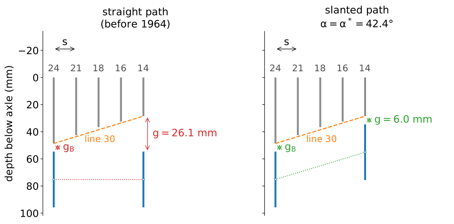
The 14–24 pack of the 1960s with the pulley at the two ends of the pack, with the same setting on the largest sprocket. Left: the straight parallelogram. Right: the slanted one. Drawn from the model; sideways distances three times larger than real.
The idea
US 3,364,762 (Tetsuo Maeda, priority Japan 1964, granted 1968) slants the parallelogram. The connecting part 16 of the support is inclined, so that the guide pulley moves along a line parallel to line 30, which joins the lower brims of the sprockets: as the pulley goes out towards the small sprockets it also rises, as the lower edges do. The three requirements of the patent are the three characteristics of the device. The first is this slanted path; the second, an engaging length nearly the same on every sprocket, follows from it; the third is a constant chain tension with a single helical spring, which also stabilizes the cage. The claim combines the slanted parallelogram, the spring on the convertor and a cable that moves the shifting body obliquely.
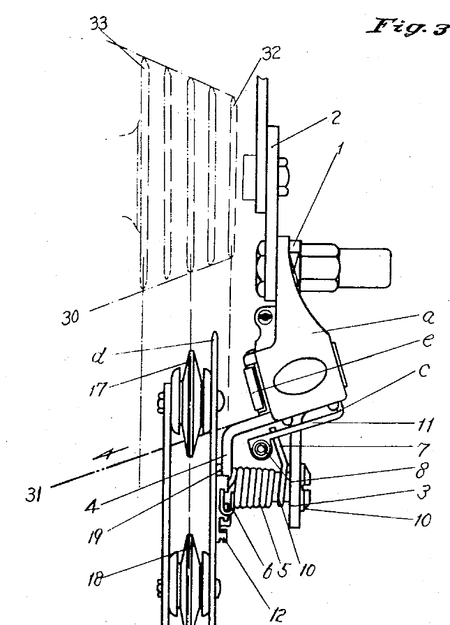
US 3,364,762, figure 3: the derailleur seen from behind with the sprockets. Line 30 joins the lower brims of the sprockets; line 31, the direction of the shifting body, is parallel to it.
Why it works
The model of the case reduces the derailleur to the path of the pulley against the profile of the pack. With the pulley set to the gap \(g_B\) under the largest sprocket, its depth under the axle is a straight line of slope \(\alpha\) in the rear view, and the gap on each sprocket follows from the radii of the sprockets (eq. 3 of the model page). Line 30 has the slope \(\alpha^*\) that makes the gap the same at the two ends of the pack: for the 14–24 pack, \(\alpha^*=42.43°\) . With this slope the gap on the 14–24 pack stays between 6.0 mm and 8.0 mm, against 6.0 mm to 26.1 mm with the straight path: the spread falls from 20.1 mm to 2.0 mm, a tenth.
The consequences follow in a chain, each link from the previous one. A small gap means a short free span: with the slanted path it stays between 25.0 mm and 31.3 mm on the whole pack. A short span is tilted steeply by one step of the cage: between 10.0° and 12.4° on every sprocket, instead of 5.5° to 10.6°. A steep tilt pushes the chain sooner onto the next sprocket, which is the argument of the patent; the model gives the geometry of it, not the capture. The change of sprocket is then about the same from the first gear to the last, with one setting.
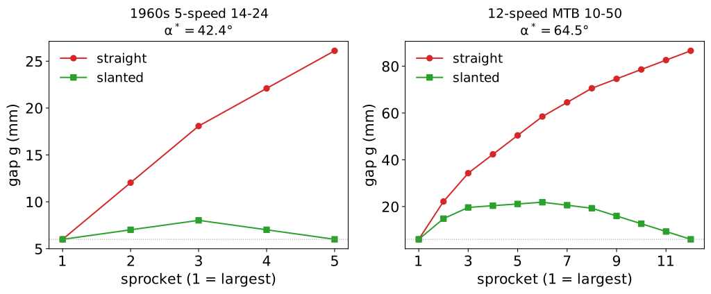
Gap on every sprocket for the straight and the slanted path, with \(g_B=6\) mm. Left: the 14–24 pack of the 1960s; right: the 12-speed 10–50 pack of today. Drawn from the model.
The explorer shows it on six packs: pick the 1960s pack, press Straight and then Slanted, and press Shift across the pack to see the free span stay short on every sprocket.
Where it stops
The idea assumes that the lower edges of the sprockets lie on a straight line, and they do so only roughly. On a narrow pack with small differences of size the error is small; the wider the pack, the more the edges depart from line 30. The model gives the spread of the gap, \(\Delta g=\max g-\min g\) , with the slanted path: 2.0 mm on the 14–24 pack, 7.7 mm on the 11–34 of an eleven-speed and 15.9 mm on the 12-speed 10–50 of today. On the last one the gap rises from 6.0 mm on the largest sprocket to 21.9 mm and returns to 6.0 mm on the smallest, and the free span, which the slanted path keeps between 23.0 mm and 63.6 mm, is no longer short in the middle of the pack. The straight path on the same pack ranges from 38.7 mm to 120.9 mm. A straight line follows the two ends of a wide pack and not the middle.
The model has limits of its own, declared on the model page: it does not include the rotation of the convertor about its pin and the spring, which move the pulley along a short arc and give the constant tension of the third characteristic; it does not model the engaging length of the second characteristic, which the patent takes to follow from the slanted path; it does not compute the capture of the chain by the next sprocket, which depends on clearances and on the shape of the teeth; and the gaps are between pitch circles, not between the tips of the teeth as a mechanic measures them. The explorer shows how the elements of the patent concur in the function; it is not a tool for setting up a real derailleur, for which the manual of the maker applies. None of these limits changes the comparison of the straight and the slanted path, which depends on the radii of the sprockets and their spacing only.
The idea does not remove the limit of the wide packs; it moves it. The other ways found since to keep the pulley close, among them a pulley set far back from the cage pivot on the derailleurs for a single chainring, are on the entry page.
Further reading
The mechanism, with the model, its assumptions and every number of this page, is on the model page. The explorer moves the pulley across the pack, with the straight or the slanted path and six packs, and shows the gap, the free span and the tilt of one step on every sprocket. The other ways of performing the same function, before and after this patent, are on the entry page.
Sources. US 3,364,762 (Google Patents). Sprocket spacings: Sheldon Brown, Sprocket spacing; Wikibooks, Bicycles/Maintenance and Repair/Shimano 11-speed. B-screw setting: Park Tool, rear derailleur adjustment.