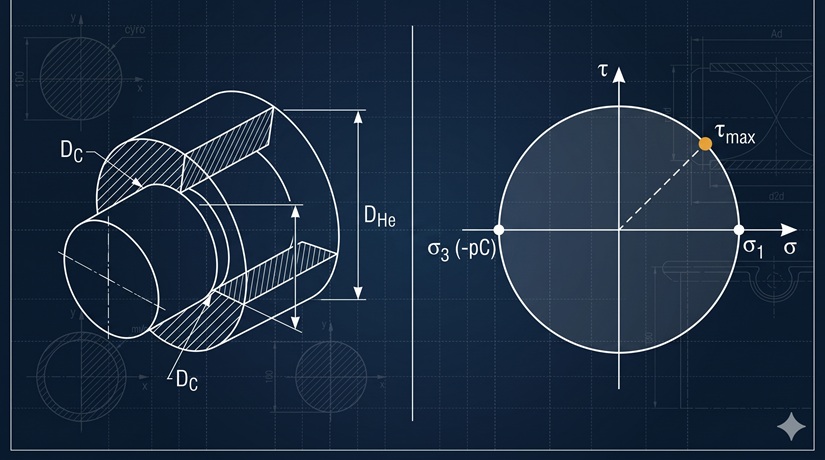
A shrink-fit hub on a shaft must transmit torque without yielding. Lamé’s equations give the stress state as a function of the contact pressure \(p_C\) and the geometry. One question remains: beyond what \(p_C\) does the hub yield?
Tresca’s criterion answers this by reducing a 3D stress state to a single scalar comparable to the uniaxial yield strength. The combination of Lamé and Tresca produces a closed-form expression for the maximum allowable contact pressure as a function of the hub geometry ratio \(Q_H\) and the yield strength \(\sigma_y\) alone.
Pipeline
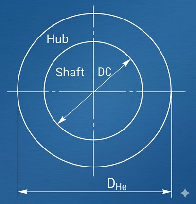
(1) Stress state at the hub inner surface
Axial symmetry makes the stress tensor diagonal in cylindrical coordinates \((r, \theta, z)\) :
The diagonal components are principal stresses. Lamé’s equations for a hollow cylinder under internal pressure \(p_C\) , evaluated at the inner radius \(r = D_C/2\) :
with:
where \(D_{He}\) is the hub outer diameter and \(D_C\) the contact diameter. The axial stress \(\sigma_z\) lies between \(\sigma_r\) and \(\sigma_\theta\) for both plane-stress (\(\sigma_z = 0\) ) and plane-strain (\(\sigma_z = \nu(\sigma_r + \sigma_\theta)\) ) configurations.
(2) Ordering of principal stresses
With convention \(\sigma_1 \ge \sigma_2 \ge \sigma_3\) :
(3) Critical Mohr circle
The governing Mohr circle is \(C_{13}\) , built on the \((\sigma_1, \sigma_3)\) pair:
The intermediate stress \(\sigma_z\) does not appear: Tresca is insensitive to \(\sigma_2\) .
Move the slider to rotate the face normal in physical space. Watch the corresponding point trace an arc on the Mohr circle. The maximum shear stress is reached at $2\theta = 90°$ from the principal direction — that is, at $\theta = 45°$ in physical space.
(4) Tresca criterion
Uniaxial tension at yield: \(\sigma_1 = \sigma_y\) , \(\sigma_3 = 0\) , hence \(\tau_{max}^{(tension)} = \sigma_y/2\) . Equating to (6):
Tresca equivalent stress:
(5) Substitution and simplification
Inserting (3) into (9):
(6) Maximum allowable contact pressure
Imposing \(\sigma_{Tresca} \le \sigma_y\) and inverting:
Closing
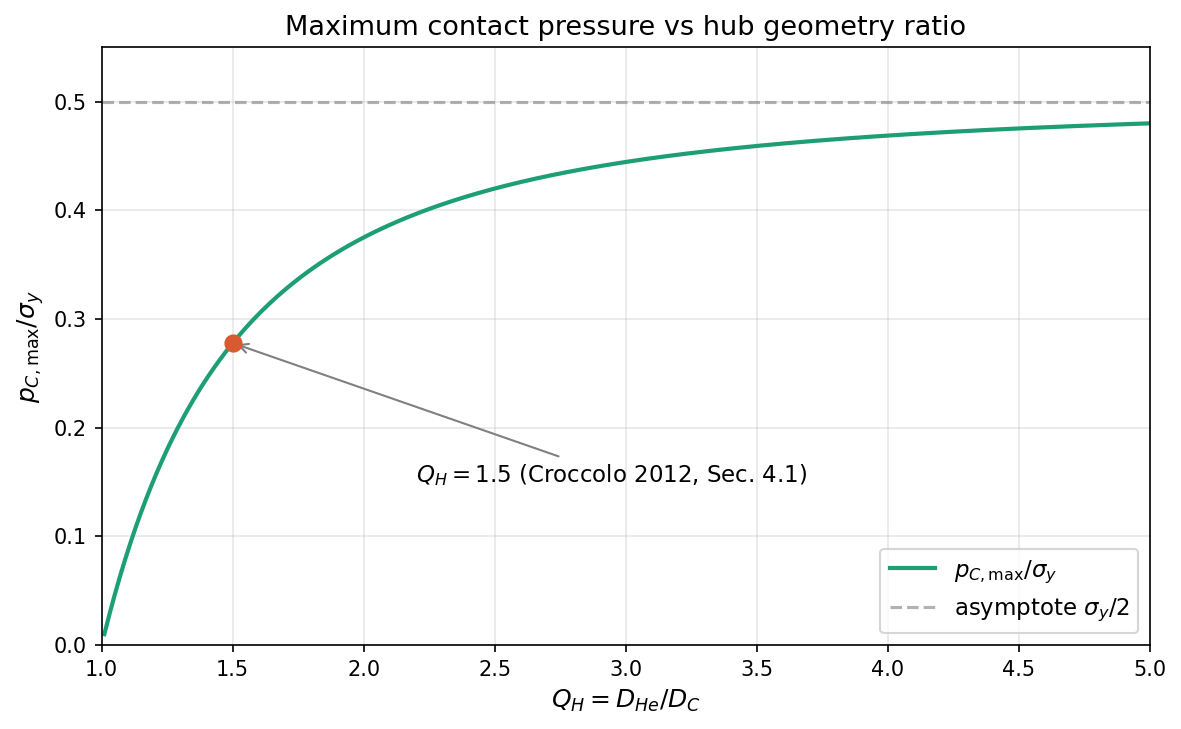
Final formula. \(p_{C,\max} = \sigma_y (Q_H^2 - 1) / (2 Q_H^2)\) .
Assumptions (in order of appearance):
- Axial symmetry (coaxial shaft and hub, \(\theta\) -independent loading) — eq. (1)
- Lamé validity: homogeneous, isotropic, linear-elastic material, small strains — eqs. (2), (3)
- \(\sigma_z\) intermediate between \(\sigma_r\) and \(\sigma_\theta\) — eq. (5)
- Tresca criterion (ductile material, slip-dominated failure) — eq. (8)
- Unity safety factor; substitute \(\sigma_y \to \sigma_y / n_s\) in design
- No friction shear on coupling surface (\(\tau = 0\) ). The full formulation including friction \(\tau = \mu p_C + \tau_{ad}\) is in Croccolo et al. (2012), Eq. (12). Formula (11) is the \(\mu = 0\) , \(\tau_{ad} = 0\) limit, which overestimates \(p_{C,\max}\) by about 2–3% for typical friction coefficients.
Numerical validity limits:
- \(Q_H \to 1^+\) : \(p_{C,\max} \to 0\) (vanishingly thin hub)
- \(Q_H \to \infty\) : \(p_{C,\max} \to \sigma_y / 2\) (semi-infinite body)
- \(p_C > p_{C,\max}\) : incipient yielding at inner surface; progressive plastification not covered by elastic Lamé
Practical use. Equation (11) sets the upper bound on the interference \(Z\) : torque transmission requires \(Z \ge Z_{\min}\) ; hub strength requires \(p_C \le p_{C,\max}\) , hence \(Z \le Z_{\max}\) . If \(Z_{\min} > Z_{\max}\) , increase \(Q_H\) , choose a stronger hub material, or add adhesive.
Maximum contact pressure vs hub geometry ratio
import numpy as np
import matplotlib.pyplot as plt

Q = np.linspace(1.01, 5.0, 400)
ratio = (Q**2 - 1) / (2 * Q**2)

fig, ax = plt.subplots(figsize=(8, 5))
ax.plot(Q, ratio, linewidth=2, color='#1D9E75', label=r'$p_{C,max}/\sigma_y$')
ax.axhline(0.5, linestyle='--', color='gray', alpha=0.6, label=r'asymptote $\sigma_y/2$')
ax.scatter([1.5], [(1.5**2 - 1)/(2*1.5**2)], color='#D85A30', zorder=5, s=60)
ax.annotate(r'$Q_H = 1.5$ (Croccolo 2012, Sec. 4.1)',
            xy=(1.5, (1.5**2-1)/(2*1.5**2)), xytext=(2.2, 0.15),
            arrowprops=dict(arrowstyle='->', color='gray'))
ax.set_xlabel(r'$Q_H = D_{He} / D_C$')
ax.set_ylabel(r'$p_{C,max} / \sigma_y$')
ax.set_title('Maximum contact pressure vs hub geometry ratio')
ax.grid(True, alpha=0.3)
ax.legend()
plt.tight_layout()
plt.savefig('pc_max_vs_qh.png', dpi=150, bbox_inches='tight')
Numerical example — Croccolo, De Agostinis & Vincenzi (2012), Section 4.1
Data from the paper’s scenario 2: hollow steel shaft (39NiCrMo3, \(Q_S = 0.7\) ) press-fitted into an aluminium hub (EN-AW6082), no adhesive. The paper computes \(p_C = 82\) MPa as the Tresca-limited maximum pressure including friction (\(\mu = 0.4\) ).
| Parameter | Symbol | Value |
|---|---|---|
| Contact diameter | \(D_C\) | 28 mm |
| Hub outer diameter | \(D_{He}\) | 42 mm |
| Hub geometry ratio | \(Q_H\) | \(42/28 = 1.5\) |
| Shaft aspect ratio | \(Q_S\) | 0.7 |
| Hub material | — | EN-AW6082 aluminium |
| Hub yield strength | \(\sigma_y\) | 304 MPa |
| Contact pressure (paper, with friction) | \(p_C\) | 82 MPa |
Calculations.
From eq. (3):
From eq. (2): \(\sigma_r = -82\) MPa.
From eq. (10):
Cross-check: \(\sigma_\theta + p_C = 213.2 + 82 = 295.2\) MPa ✓
Safety factor: \(n_s = 304 / 295.2 = 1.03\) .
From eq. (11):
Interpretation. The simplified formula (11) gives \(p_{C,\max} = 84.4\) MPa. The paper reports 82 MPa from the full Tresca criterion including friction (\(\mu = 0.4\) ). The 2.9% difference confirms that friction has a modest effect on the yield limit. The safety factor \(n_s = 1.03\) indicates that 82 MPa is essentially at the Tresca limit — as expected, since the paper computed it as the maximum allowable pressure.
For a case with a more comfortable margin: at \(p_C = 67\) MPa (the paper’s hybrid scenario with adhesive), \(\sigma_{Tresca} = 67 \times 3.6 = 241.2\) MPa and \(n_s = 304/241.2 = 1.26\) .
References
- Croccolo D., De Agostinis M., Vincenzi N. (2012), “Design and optimization of shaft–hub hybrid joints for lightweight structures: Analytical definition of normalizing parameters”, Int. J. Mechanical Sciences, 56, 77–85.
- Croccolo D., Vincenzi N. (2009), “A generalized theory for shaft–hub couplings”, Proc. IMechE Part C, 223, 2231–2239.
- Timoshenko S., Goodier J.N. (1970), Theory of Elasticity, McGraw-Hill, 3rd ed.
Related: Thick-Walled Cylinder Stress Analysis (Croccolo 2009)